XB259 - The Exterior
The Undercarriage
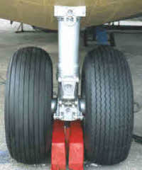
ABOVE LEFT: The Nose Wheel.
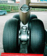
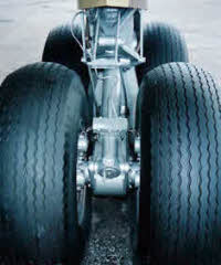
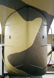
ABOVE CENTRE & RIGHT: The starboard main gear from the front and rear. The original design for the GAL Universal Freighter had a single large wheel for the wing undercarriage units. This was changed to a safer four wheel bogie design for the production Beverleys.
The Beverley had a robust fixed tricycle undercarriage. Steering was by means of a Lockheed twin-wheel nose wheel assembly, giving the Beverley a 33 feet (10.15 metre) turning circle, better than many cars.
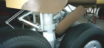
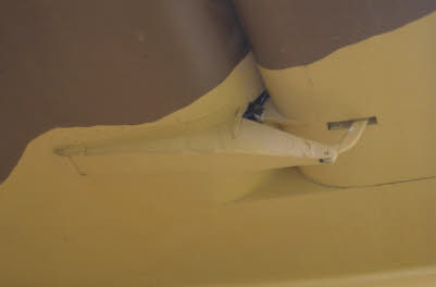
LEFT: A side-view of the starboard bogie. Just below the vertical strut, there is a piece with vertical lines showing. This is not part of the undercarriage, but a support for the oleo, which has been fitted to take strain away from the oleo assembly. The fairing angled forward on the right would move to a vertical position when the aircraft was airborne and no load was bearing down on the landing gear.
The main wheels were 4–wheel bogie units fitted with Dunlop anti–skid braking units. The bogies were attached to the main spar by Lockheed oleo struts. An aerofoil section between the strut and the fuselage, provided bracing for the assemblies. In flight, bogie wheels adopted a visible ‘nose-up’ attitude.
![]()
The Boom & Tail
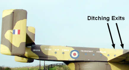
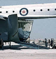
Thirty-six passengers or 30 paratroops could be carried in the Boom, The same numbers as the Hastings Transport could carry. Entry to the boom was by means of two trap doors at the front in the floor leading to the Freight Bay, or through the paratroop doors in the floor at the rear of the Boom. There are four ditching exits at the front of the Boom, two on each side. Dinghies were stowed in the wings.
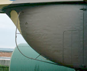
ABOVE LEFT: The span of the tail-plane is 42 feet (12.9 metres) and each of the tail planes has an enormous 196 square foot rectangular fin and rudder at the tip, the top of which are almost 39 feet above ground. The complete Tail Plane and Fin and Rudder assembly is attached to the boom by only four large high tensile steel bolts.
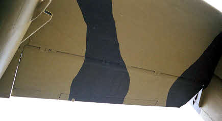
ABOVE RIGHT: The port Tail-Plane assembly from below, showing the junction with the fin and rudder. The trim tabs on the rudder and the elevator can easily be seen. Air intakes can also be seen on the side of the boom. Similar intakes are on the opposite side of the Boom as well.
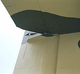
LEFT: The port rudder where it joins the tail plane. A rudder trim tab can be seen in the photo.
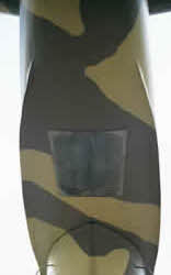
RIGHT: The paratroop exit. This has been covered by a clear plastic sheet. There are two sideways opening doors beyond the sheet which have been fastened in the open position.
The toilets are situated in the tail of the Beverley, beyond the paratroop doors. A fatality occurred when a serviceman fell the twenty feet to the ground when coming out of the toilet, not knowing that the doors had been opened. Modifications were then made to prevent the toilet doors from being opened when the paratroop doors were open.
![]()
Clamshell Doors & Nose
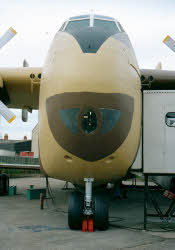
ABOVE LEFT: The nose showing the Navigator’s position above the nose wheel. The Navigator would be stationed here for air-drops of supplies or for para trooping.
ABOVE CENTRE: Two photos of the Clamshell doors at the rear of the Freight Bay. The rails attached to the Clamshells were fitted when the Beverley was dropping paratroops. These prevented the parachute static lines and bags from tangling behind the doors. Circular ventilators are in each door. Each Clamshell had an inwardly folding door in the side. As well as paratroops dropping, they were used for supply dropping and loading passengers.
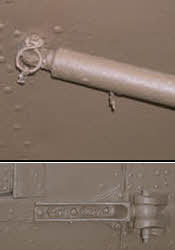
ABOVE RIGHT: An attachment point for anti-snagging rails (top) and a door hinge (bottom).
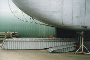
 ABOVE LEFT: Clamshell Doors open and Ramps and ‘Elephant’s Foot’ fitted for loading.
ABOVE CENTRE: Each of the two Ramps has two pieces, normally hinged. The Ramps are carried inside the doors. They were attached by hinges to the sill at the rear of the Freight Bay. Electric motors raised and lowered the Ramps.
ABOVE RIGHT: The ‘Elephant’s Foot’ was attached to the rear of the Freight Bay when loading heavy items. It was designed to prevent the aircraft tipping backwards. This, like the rails was held on by pins.
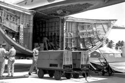
LEFT: Part of a Beverley load. The Ramps are down and there is an array of staging and equipment stored in the Clamshell Doors.
![]()
The Wings & Engines
ABOVE LEFT: : The Beverley has a wing span of 192 feet with a surface area of 2916 square feet.
Eight fuel tanks in the wings held 6950 gallons of Avgas.
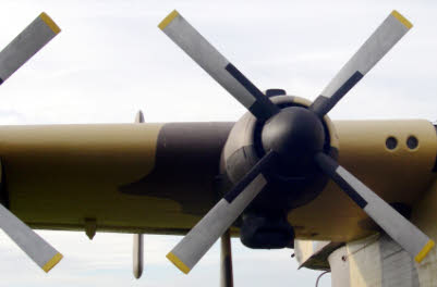
ABOVE LEFT: One of the Centaurus Engines with, to the right, air intakes for the de-icing system.
ABOVE RIGHT: A flap actuating control on the starboard wing.
The Beverley was powered by four Bristol Centaurus 173 or 175 air-cooled 18 cylinder, two row, sleeve-valve radial engines. The engines developed 2850HP each at maximum power using water-methanol injection. The engines were not the most reliable of Bristol’s aero engines, thereby selling the Beverley short, but they did have to take a lot of punishment on the Beverley, particularly in the middle east. The propellers are 16’6” De Havilland Hydromatic of hollow steel construction. They are fully feathering with auto-coarsing and reverse pitch systems. The reverse pitch gave the ‘Bev’ its incredibly short landing run, and was not available on the turbine engines of the day. The height of the engines above the ground meant that special equipment was required to service and change them.