XB259 - The Freight Bay
The Beverley was the largest aircraft in service when it joined the RAF and it had, for those days, a truly cavernous Freight Bay. The Bay is 36 feet (10.97 m) long and 10 feet (3.05 m) wide and 10 feet high, and thanks to the wide opening clamshell doors, could take on board very large objects and vehicles. Aircraft such as the Folland Gnat were also carried as were helicopters such as Whirlwinds. Odd loads such as the Lord Mayor of London's coach, and an East Yorkshire bus were also among the myriad of things Beverleys carried.
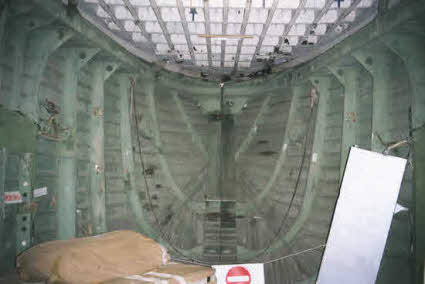
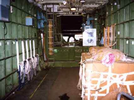 Looking forward along the Freight Bay of XB259. This photograph was taken when it was at the Museum of Army Transport. To the left of centre in the photograph can be seen the ladder which leads up to the flight deck. Five folding paratroop seats are fitted to the left fuselage side. The two large containers to the right are 1 Ton (1016 kg) Containers used for the air-dropping of supplies. Up to sixteen of these would be carried. The Navigator’s position in the nose is in the centre of the photo.
Loads were secured to the floor by means of removable swivel ring type strong points laid out in a 20 inch (508mm) grid. These strong points could take a strain of 10,000lbs (4536 kg). Items could also be lashed to the rails running along the side walls of the bay. There are 7 rows of Strong Points.The centre row has seven additional strong points with a strain of 21,000Lbs (9525 kg). These are accessed by removing cover plates in the floor. The fittings for these were used to restrain heavy-drop platforms. Lashing rings were stored in slotted plates fixed to the side walls of the Freight Bay. Chains, lashings and tensioners were stored in pockets at floor level in the walls.
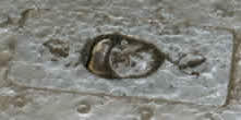 RIGHT: A 10,000Lb Strong Point in the floor.The nose of the aircraft is to the right. A lashing ring was pushed down over two spring loaded catches in the widest part of the strong point and pushed forward. The rearmost catch then sprang up locking the ring in position. Removal was by simply pushing down the rear catch with a probe and pulling the ring and up.
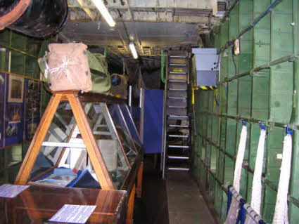
ABOVE LEFT: Looking aft on the port side. One of two staircases normally only fitted in a passenger carrying role. The rails along the sides made a handy ladder at other times. The box by the ladder to the right is an air-conditioning unit, fitted to help preserve the aircraft. Such a device would have been a godsend in the middle and far east. Air Despatch exhibits are arrayed down the centre of the Freight Bay and photographs are displayed on the walls.
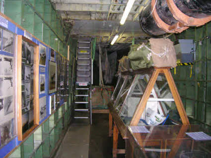
ABOVE RIGHT: Looking down the starboard side. The range of photos on display is easily seen. The black container top left is a CLE (Container Light Equipment) These were designed to be dropped from bomb racks and were not used on Beverleys. On top of the glass cass is a SEAC (South East Asia Command) Pack. These carried loads of up to 185Lbs. An 18ft parachute was used for these.
ABOVE LEFT: The enormous Clamshell Doors are electrically operated and each contains a folding parachute door. They were also used to store staging and servicing equipment when fitted to the Beverley. The silver door on the right is the port entrance/parachute door folded open. One of two locking catches is shown at the bottom of the photo.
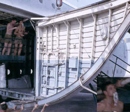
ABOVE RIGHT: A Clamshell being removed or re-fitted. Peter Langton took this in Aden circa 1961. That's one heck of a dummy the ‘Erk’ is sucking!
 LEFT: Door Mechanisms
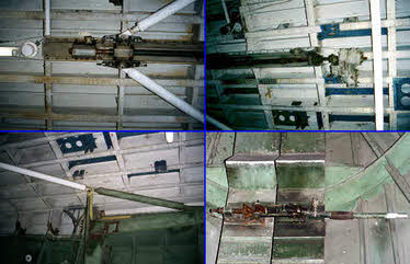
Top Left & Right: The Clamshell Opening Mechanism on the ceiling of the Freight Bay. The electric motor (right) drives a screw shaft via a flexible coupling. The shaft moves the white bars (left) forward or backward.
Bottom Left: The white bars push or pull on the green bars which push the doors open or pull them shut.
Bottom Right: The lower of two locking clamps fitted to keep the doors firmly closed. Rather important clamps indeed.
When air dropping containers or platforms, roller conveyor tracks were fitted to the floor. In the later years of the Beverley's service, Side Guidance Rails would be used for platforms. These attached to the floor and had built in restrains which held the platform in place during flight.
RIGHT: 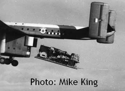 Platforms were pulled from the aircraft by 10ft or 21ft Ring Slot extractor parachutes, depending on the weight of the platform. Four Boscombe Down Platforms ( Supply Stressed Platforms) of 8,000Lbs could be carried or two Medium Stressed Platforms or one Heavy Stressed Platform. Loads would vary from supplies, vehicles, armoured vehicles, bulldozers, graders etc.
The photo shows a Grader on a Heavy Stressed Platform leaving a Beverley. the cable to the extractor parachute is to the right. Six 66 Foot parachutes are on the right of the platform.
When in the Heavy Drop Role, a pair of air deflectors were fitted at the rear of the Freight Bay. Seen in the photo, they were called ‘Elephant’s ears’.
Between four and sixteen 1-Ton Containers would be carried for automatic ejection, although three were known to have been dropped in automatic ejection. A small S80-Inch extractor parachute would be deployed by the Navigator. This would release pins fitted to metal boxes on a two part barrier holding the containers in the aircraft. Bungee cords would then pull the barrier apart and gravity would take over and the containers poll over the sill. The Pilot held the aircraft ar a 5° nose-up attitude during these drops to help the containers on their way. For automatic ejection, two Army Air Despatchers would be carried. These men would remove restraints from the containers just before the drop. A crew of four Air Despatchers would normally be carried for manual ejection. One or two containers would be dropped on each pass over the dropping zone. The Despatchers holding the containers in until the green light came on, then they would push them out.
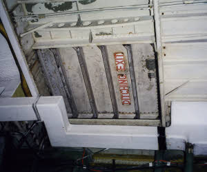
 LEFT: One of the two Ditching Exits in the Freight Bay.
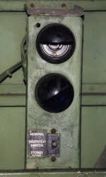
RIGHT: A set of Despatch Light in the Freight Bat. The Red lens is missing. Below them are switches for a camera which was fitted on the sill at the rear of the Freight Bay.
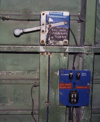
FAR RIGHT: An Extractor Parachute Release Handle on the Starboard side.
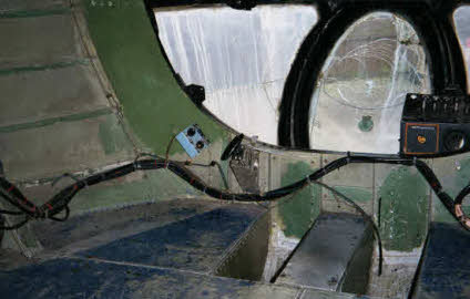
ABOVE LEFT & RIGHT: The raised portion of the Freight Bay forward of the front entrance door is called the ‘Bandstand’. When the Beverley was dropping supplies or paratroops, the Navigator sat here with his feet in the slots in the floor. 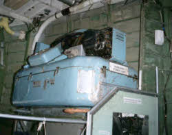 He would have an excellent view of the dropping zone through the Clearview panel, and would direct the Pilot onto the CARP (Calculated Aerial Release Point). The Navigator operated the dropping lights, red for stand by, and green for go. These were on the walls just in front of the clamshell doors and in the boom by the parachute exit. For heavy drops, he would pull the handle on the left. This would release the extractor parachute to pull the load from the aircraft.
RIGHT: Fitted on the starboard side of the ‘Bandstand’ is an Auxiliary PSU (Power Supply Unit). This was required as the Beverley required its own power source for starting engines at remote airstrips.